Data Center Solutions
Project Overview
This solution addresses the construction needs of data centers with a capacity of 6300kVA, 35kV-0.4kV voltage level, dual-system architecture, and Class 1 energy consumption requirements. It integrates the latest technical standards and energy-saving concepts in the data center industry, designing comprehensively from the power system, cooling system, cabinet layout, to intelligent operation and maintenance. The solution focuses on achieving "high reliability, low energy consumption, easy scalability, and maintainability," ensuring that the data center meets the Class A room standards specified in GB50174-2017 "Design Code for Data Centers." It also achieves Class 1 energy consumption metrics (PUE ≤ 1.25), providing a continuous and stable operating environment for business systems. This makes it suitable for scenarios with stringent requirements for reliability and energy efficiency, such as finance, internet, and enterprise-level core operations.
01 Core Requirements Analysis
01 Core Electricity Demand
Capacity matching
To meet the total load demand of 6300kVA, with IT equipment accounting for approximately 4500kVA and supporting facilities (cooling, lighting, and O&M) contributing about 1800kVA, precise load distribution and dynamic adjustment must be implemented.
Voltage level conversion
Enables efficient conversion from 35kV high-voltage to 0.4kV low-voltage distribution, ensuring voltage stability with fluctuations controlled within ±5%.
Dual-system redundancy
The architecture features two fully independent power systems with seamless failover capability. Even if one system fails, business operations remain unaffected, meeting the "N+1" redundancy standard.
02 Energy Consumption and Reliability Requirements
Level 1 energy efficiency standard
The data center's PUE value must be consistently maintained below 1.25, with the primary focus on reducing energy consumption from non-IT equipment, particularly in cooling systems and power conversion losses.
High reliability
With an average annual mean time between failures (MTBF) of ≥100,000 hours and mean time to recovery (MTTR) ≤30 minutes, it ensures 7×24-hour uninterrupted operation for core business.
03 Other key requirements
Scalability
Reserves 20% of power capacity and cabinet space to accommodate future business growth and equipment upgrades.
Safety and Compliance
Complies with national standards for power safety, fire protection, and environmental protection, and has obtained ISO 27001 Information Security Certification and Green Data Center certification.
Smart O&M
Enables real-time device status monitoring, precise energy consumption analysis, automatic fault alerts, and remote maintenance.
02 Overall Design Framework
This solution employs a "modular, dual-redundant, fully intelligent" design architecture, with four core modules: power system, cooling system, cabinet and wiring system, and intelligent operation and maintenance system. Each module operates independently with redundancy while maintaining coordinated interaction, ensuring the overall system's reliability and energy efficiency. The specific architecture is as follows:
Power module
35kV dual-circuit access → high-voltage distribution → dual main transformers → low-voltage distribution → UPS/panel → IT equipment, achieving 'physical isolation of dual systems and dynamic load distribution'.
The refrigeration module
Combines inter-row precision air conditioning with natural cooling sources, forming a closed cold channel and enabling hot air recirculation to achieve 'precision cooling and on-demand cooling'.
Rack wiring module
High-density rack layout → Micro-module encapsulation → Structured cabling, improving space utilization and cabling standardization.
Intelligent O&M module
Unified monitoring platform → Energy consumption analysis system → Fault early warning mechanism, enabling end-to-end visual management.
03 Core System Design Details
01 Power System Design (Core Module)
35kV Access and High Voltage Distribution System
The system employs dual 35kV high-voltage circuits with independent power supply from separate substations to ensure operational independence. The high-voltage distribution system features two independent gas-insulated switchgear (GIS) units, each containing incoming, metering, PT, and outgoing cabinets for independent control of the dual main transformers. Designed with a capacity of 6300 kva per unit, the system supports 100% load operation under single-system conditions to meet redundancy requirements. Additionally, high-voltage automatic transfer switchgear ensures uninterrupted power supply by automatically switching to the backup power source within 0.5 seconds in case of a primary power failure.
Main Transformer System Design
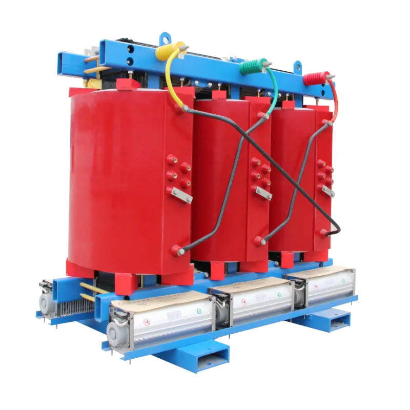
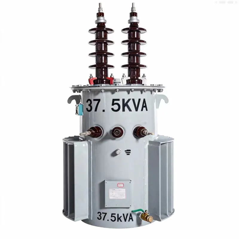
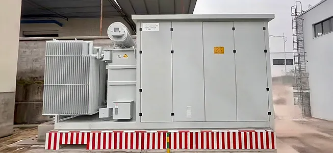
The system includes two 6300kVA oil-immersed power transformers (or dry-type transformers, selected based on the server room environment), model S13-M-6300/35 (S13 series with Class 1 energy efficiency rating, delivering over 20% lower losses than conventional transformers). These transformers feature a Dyn11 connection configuration with 35kV high-voltage and 0.4kV low-voltage sides, utilizing a double-split winding design to enable independent operation of two low-voltage systems and balanced load distribution. Equipped with intelligent temperature control systems and online monitoring devices, they provide real-time monitoring of oil temperature, oil level, and insulation status, automatically triggering alarms and cooling mechanisms when abnormalities are detected.
Low-voltage Distribution and UPS System
The low-voltage power distribution system employs a dual-bus architecture with two fully independent subsystems. Each subsystem is equipped with drawer-type switchgear containing incoming line cabinets, capacitor compensation cabinets, and feeder cabinets. The capacitor compensation cabinets utilize a Dynamic Var Generator (SVG) with ±1kvar compensation accuracy, maintaining a stable power factor above 0.95 to minimize reactive power loss.
The UPS system employs a "modular UPS + lithium battery" configuration, with each unit comprising four 200kVA modular UPS units operating in N+1 redundant mode (three active, one standby), delivering a total capacity of 4500kVA to meet IT equipment demands. The UPS modules achieve ≥96% efficiency under full load and ≥92% under light load (20%), surpassing industry benchmarks. The battery pack utilizes lithium iron phosphate (LFP) technology, replacing traditional lead-acid batteries with a 50% reduction in size and over 10-year lifespan. Featuring a 95%+ charge-discharge efficiency, the system is equipped with a Battery Management System (BMS) for real-time state monitoring and balanced charging.
Headboard Cabinet and Power Distribution Terminal
Each cabinet zone features dual-row head cabinets connected to two low-voltage systems, providing dual power supply at the cabinet level. These cabinets are equipped with smart meters and PDU (Power Distribution Unit) units, enabling real-time monitoring of current, voltage, and power for each output channel with 0.5-class precision, which provides data support for energy consumption analysis. The PDU adopts a high-density socket design with hot-swappable capability, meeting the power supply requirements of servers, storage devices, and other equipment.
02 Refrigeration System Design (Energy Conservation Core)
Selection of Cooling Solutions
The hybrid cooling solution of "inter-row precision air conditioning + natural cold source" combined with closed cold aisle technology maximizes cooling efficiency. Deployed adjacent to IT equipment, the inter-row air conditioning units direct airflow to the cabinet's intake side, reducing cold air delivery distance and cutting cooling loss by over 30%. The closed cold aisle completely isolates cold and hot air, preventing thermal mixing and further enhancing cooling performance.
Equipment Configuration and Operation Mechanism
The facility is equipped with 1240kW row-level precision air conditioners, organized into two dual power system configurations (N+1 redundancy, 6 units per system). These units feature EC (Electronic Commutation) fans with ≥90% efficiency and variable-speed control for IT load dynamics. The compressors utilize variable frequency technology, delivering 10%-100% cooling capacity adjustment to match load variations.
When outdoor temperatures are ≤15℃, the system automatically switches to natural cooling mode, using plate heat exchangers to draw in outdoor cold air for direct cooling of the server room. In this mode, the air conditioning compressor stops running, with only the fan consuming energy, reducing cooling energy consumption by over 70%. When outdoor temperatures exceed 15℃, the system switches to mechanical cooling mode to maintain stable server room temperatures between 20-24℃ and humidity levels of 40%-60%.
03 Cabinet and Wiring System Design
Cabinet Layout and Configuration
The system employs a "micro-module" cabinet layout, with each module containing 16 high-density 42U cabinets, two row-level air conditioners, and enclosed cold aisles, while maintaining 1.2-meter maintenance access between modules. The cabinets are constructed from high-strength cold-rolled steel plates with a load capacity of ≥1000kg, featuring front/rear perforated doors for ventilation efficiency of ≥75% to ensure optimal heat dissipation. Each cabinet is equipped with two intelligent PDU units connected to dual-row head cabinets, providing dual power redundancy.
Wiring System Design
The cabling system employs a "top-pairing + cable tray" configuration, featuring separate power and network cable trays for physical isolation to prevent interference. Power cables use YJV (Y-junction voltage divider) cross-linked polyethylene insulated cables with flame-retardant properties and sufficient current-carrying capacity. Network cables utilize Category 6 unshielded twisted pair and single-mode fiber, supporting 10Gbps transmission rates to accommodate future service upgrades. The system adheres to structured and standardized principles, with clear labeling for easy maintenance and expansion.
04 Design of Intelligent Operation and Maintenance System
Unified Monitoring Platform
The IoT-based unified monitoring platform integrates full-chain data from power systems, cooling systems, cabinet equipment, and environmental parameters (temperature, humidity, smoke detection, water ingress) to enable "one-map" visual management. Supporting real-time data collection (frequency ≤1 second), device status display, and trend analysis, the platform provides PC and mobile access, allowing maintenance personnel to monitor data center operations in real time.
Energy Consumption Analysis and Optimization
The platform features an integrated energy consumption analysis module that aggregates data across systems, modules, and cabinets. It calculates PUE values (with updates every 15 minutes) and generates detailed energy consumption reports with trend analysis. By comparing energy usage across different regions and time periods, the system identifies high-consumption areas, providing actionable insights for energy efficiency optimization. For example, when a region's PUE shows abnormal spikes, the platform automatically analyzes whether this stems from mismatched cooling loads or equipment malfunctions, then delivers targeted optimization recommendations.
Fault Warning and Intelligent Linkage
The system presets equipment failure thresholds (e.g., transformer oil temperature ≥85°C, UPS load ≥80%, and server room temperature ≥26°C). When monitoring data exceeds these thresholds, it automatically triggers multi-level alerts (acoustic/visual alarms, SMS notifications, and APP push alerts) while precisely locating fault locations and causes. It also supports intelligent coordination: for instance, when detecting temperature rise in a specific area, it automatically adjusts the air conditioner speed in that zone; when a power supply fails, it automatically activates the automatic transfer switch (ATS) and UPS redundant modules to achieve automated fault handling.
04 Energy Consumption Optimization Strategy (Level 1 Energy Consumption Guarantee)
01 Energy conservation at the equipment level
Select Class 1 energy-efficient equipment
The main transformer uses S13 series, the UPS adopts modular high-efficiency models, and the air conditioning system employs EC fans with variable-frequency compressors, reducing the equipment's energy consumption by 20%-30%.
Lithium batteries replace lead-acid batteries
By reducing charging losses, extending service life, and lowering replacement frequency and environmental costs.

02 System-level energy conservation
Deep utilization of natural cold sources
By maximizing the use of outdoor natural cold sources through plate heat exchangers, the annual mechanical refrigeration operation time can be reduced by over 6,000 hours, and the refrigeration energy consumption can be reduced by 70%.
Optimized reactive power compensation
SVG-based dynamic compensation maintains the power factor above 0.95, effectively reducing line and transformer losses.
Closed cold aisle technology
Prevents hot and cold air mixing, increases the temperature difference between supply and return air to over 15℃, and boosts cooling efficiency by 30%.

03 Energy Conservation at the Management Level
Dynamic load regulation
The intelligent O&M platform monitors IT equipment load and dynamically adjusts UPS output and air conditioning cooling capacity to prevent underpowered operation.
Energy efficiency evaluation mechanism
Establish a statistical and assessment system for energy consumption, incorporate the PUE metric into operational management objectives, and drive the implementation of energy-saving measures.
05 Safety and Compliance Design
Electrical Safety
High-voltage systems are equipped with overcurrent, overvoltage, short-circuit, and grounding protection devices, while low-voltage systems feature leakage current and overload protection devices to ensure equipment and personnel safety.
The TN-S grounding system is adopted with a grounding resistance of ≤1Ω, ensuring reliable grounding for cabinets, equipment enclosures, and cable trays to prevent electrostatic and leakage current incidents.
Fire Safety
The computer room is equipped with a gas fire extinguishing system (septapropylene), which works in conjunction with smoke and temperature detectors to provide automatic fire alarm and suppression.
Fireproof sealing materials are installed in the cabinet area, and fireproof measures are applied to cable trays, ventilation ducts, and other components crossing fire compartments to prevent fire spread.
Compliance Assurance
The plan complies with the following standards and specifications:
GB 50174-2017 Data Center Design Code (Class A)
GB 50052-2009 "Code for Design of Power Supply and Distribution Systems"
GB 50016-2014 "Code for Fire Protection Design of Buildings"
ISO 27001 Information Security Management System Requirements
GB/T 39559-2020 (Green Data Center Evaluation Standard) Level 1
06 Project Implementation Plan
|
Stage |
Time period |
Core Task |
|
Requirement confirmation and design |
Weeks 1-4 |
Refine requirements, complete construction drawing design, equipment selection and bidding |
|
Data center renovation and infrastructure construction |
Weeks 5-12 |
Data center renovation, floor reinforcement, cable tray installation, and grounding system installation |
|
Equipment installation and commissioning |
Weeks 13-20 |
Installation and single-machine debugging of electrical equipment, refrigeration equipment, cabinets, UPS, etc. |
|
System integration and testing |
Weeks 21-24 |
Dual-system joint debugging, load testing, PUE verification, and fault simulation testing |
|
Acceptance and Delivery |
Week 25 |
Third-party testing, compliance acceptance, document delivery, and O&M training |
07 After-sales Service and Guarantee
Operation and Maintenance Support
Enjoy 1 year of free on-site maintenance with a professional team (including electrical, refrigeration, and IT engineers) available 24/7. After the first year, we offer paid maintenance services to ensure long-term stable operation of your data center.
Equipment Warranty
Core equipment (transformers, UPS, air conditioners, precision cabinets) comes with a 1-year warranty, offering free repair or replacement of faulty components. A lifecycle management system is established to monitor equipment and provide early warnings of aging risks.
Technical Upgrades
We provide regular technical inspections and system optimization recommendations. When new energy-saving technologies or standards emerge in the industry, we offer upgrade solutions to ensure data centers consistently meet Grade 1 energy efficiency requirements and support business growth.
08 Summary of the Advantages of the Plan
High reliability
The dual-system full redundancy design ensures no single point of failure from high-voltage access to IT endpoints, meeting Class A data center standards.
Ultra-efficient
Combining Class 1 energy-efficient devices, natural cooling, and smart regulation, it maintains a stable PUE (Power Usage Effectiveness) of ≤1.25, saving over 1 million kWh annually.
Intelligent and efficient
Full-chain monitoring and automated coordination boost O&M efficiency by 50% while reducing fault response time to minutes.
Flexible scaling
The modular design reserves 20% capacity, enabling rapid expansion and device upgrades to meet business growth needs.
Compliance and security
Meets multiple national standards and has obtained green and safety certifications to ensure compliant operations.
-
Previous:
None